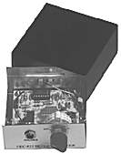
I radiofaristi di NDBlist continuano a sfornare progetti interessanti. L'ultimo è stato proposto dal grande Steve Ratzlaff e consiste nelle modifiche da lui ideate per ridurre la larghezza di banda di un filtro audio disponibile in kit di montaggio (volendo anche in versione già assemblata) da Vectronics. Questo produttore fornisce accessori e apparati di qualità agli appassionati di radioamatori e il suo filtro a 8 poli VE-821K offre di default eccellenti prestazioni a un piccolo prezzo. Il dispositivo, pensato per l'ascolto del morse (sì, lo usano ancora anche se non serve più in sede di esame per la licenza di OM, neppure più negli USA), lavora su tre larghezze di banda 180, 110 e 80 su una frequenza centrale di circa 750 Hertz. Per molti radiofaristi questo valore è troppo elevato, di solito per l'ascolto dei radiofari si preferisce lavorare tra 450 e 550 Hz. Ecco quindi la prima modifica effettuata, per poter regolare a piacere la frequenza centrale di filtro passabanda, che di base è fissa.
La seconda modifica riguarda la larghezza di banda, che Steve è riuscito a ridurre di un ordine di grandezza portandola (circa 8 Hz) su valori simili a quella del filtro superstretto già descritto qui su RP e realizzato anche da Aldo Moroni.
Il sito Web Vectronics è molto facile da navigare e il catalogo vale una visita: ci troverete molte cose interessanti. In Europa i kit si possono ordinare anche da Waters & Stanton in Gran Bretagna. C'è anche un dealer italiano, IL Elettronica, ma non vedo i kit che ci interessano: l'821K descritto da Steve, la versione 820 senza l'amplificatore audio dell'821 e il nuovo 841K e W (quest'ultima versione è già assemblata), filtro passabanda/notch con centro frequenza variabile da 30 a 3000 Hz adatto per il CW e l'ascolto della SSB.
Once the filter was assembled and working properly I wanted to see if the center frequency could be adjusted. I prefer a much lower frequency, 440 Hz. I found that adding a 100 kohm/10 turn trimpot in series with each of four resistors (R5, 10, 13, 15), that the center frequency could be readily changed over a wide range. All four pots are set to the same value, from 79
kohms at 400 Hz to 10.9 kohms at 650 Hz, as examples. (I measured the resistance needed from 400-750 Hz, in 50 Hz steps.) With the relatively wide filter bandwidth, nothing else is needed--just set the pots to the correct resistance for the associated desired new center frequency. One end of each resistor is easily unsoldered from the board and the pot added in series, on top of the board. This would allow using the filter with most any receiver that didn't have a CW filter, and give a worthwhile 80, 110, 180 Hz filter bandwidth, and allow changing the center frequency (assuming the radio allows changing the center frequency) to the user's preferred pitch.
La seconda modifica riguarda la larghezza di banda, che Steve è riuscito a ridurre di un ordine di grandezza portandola (circa 8 Hz) su valori simili a quella del filtro superstretto già descritto qui su RP e realizzato anche da Aldo Moroni.
The same four resistors (R5, 10, 13, 15) are removed and replaced with a 1 kohm/10 turn trimpot. Depending on desired bandwidth, pairs of much larger capacitors (8 total) are placed in parallel with the existing 0.001 uF poly caps. I tried 3 different values, measuring the bandwidths that resulted.
0.01 uF caps give -3dB bandwidths of 8, 10, 19 Hz. For a 440 Hz center frequency, each pot was in the 690 ohm range.
0.012 uF caps give 7, 8, 16 Hz. (Pot value for 440 Hz was about 416 ohms.)
0.015 uF caps give 6, 7, 14 Hz bandwidth. (Pot value for 440 Hz was about 270 ohms.)
The 0.015 uF caps give an equivalent bandwidth to the audio filter I'm now using, 6 Hz. This would be the version I'd use if I were making this filter for myself.
The capacitors should be high quality low-loss stable types, such as mylar, polyester, polystyrene, polypropolene or equivalent. Do not use disk ceramics unless they're NP0 or COG types! They are simply soldered on the bottom of the board across the four existing pairs, C18/19; C16/17; C14/15; C12/13. If possible each pair should be matched for best/narrowest bandwidth (I matched each pair in my tests). Only pairs should be matched, as the pots will be adjusted for the same center frequency for each of the four pairs. Or, some distributors such as Mouser sell caps in various tolerances--use at least 2% or better tolerance if you don't have the ability to match caps. Simply buy the caps and use them without matching. That will certainly give a good narrow filter, though it may be a little wider than the bandwidths I obtained using matched caps.
Of course the four variable resistors can be adjusted to operate over any desired center frequency range from 350-850 Hz. You will need a way to precisely measure filter output amplitude in order to tune up the filter, as each resistor is adjusted for maximum amplitude output at the desired center frequency. Tuning is very sharp for the very narrow bandwidths, so multi-turn trim pots are needed. Be sure to set the rotary switch to the narrow bandwidth position before beginning alignment.
Il sito Web Vectronics è molto facile da navigare e il catalogo vale una visita: ci troverete molte cose interessanti. In Europa i kit si possono ordinare anche da Waters & Stanton in Gran Bretagna. C'è anche un dealer italiano, IL Elettronica, ma non vedo i kit che ci interessano: l'821K descritto da Steve, la versione 820 senza l'amplificatore audio dell'821 e il nuovo 841K e W (quest'ultima versione è già assemblata), filtro passabanda/notch con centro frequenza variabile da 30 a 3000 Hz adatto per il CW e l'ascolto della SSB.
Tags: radioascolto, radiofonia, radio, dxing.
Nessun commento:
Posta un commento